- 您现在的位置:买卖IC网 > Sheet目录2011 > MAX5893EGK+D (Maxim Integrated Products)IC DAC 12BIT DUAL 500MSPS 68-QFN
MAX5893
12-Bit, 500Msps Interpolating and Modulating
Dual DAC with CMOS Inputs
______________________________________________________________________________________
19
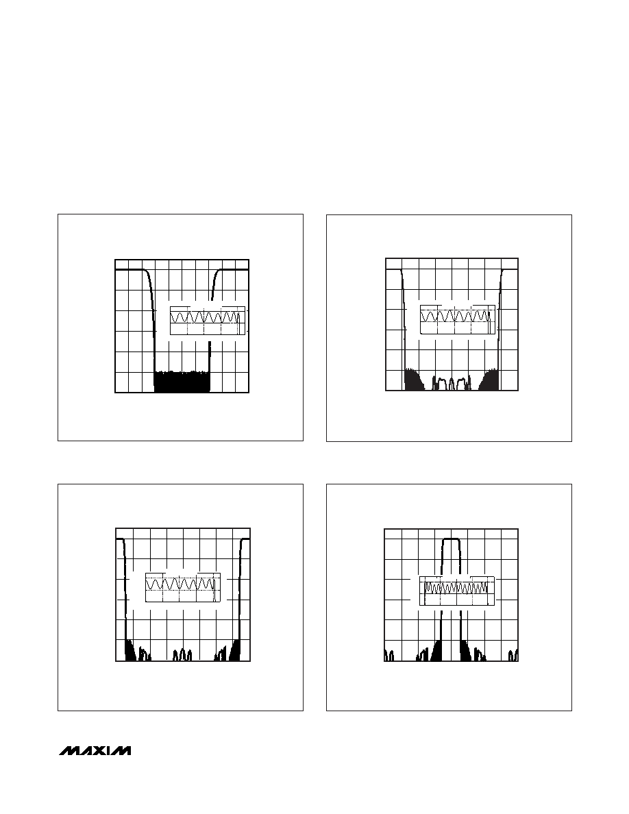
Interpolating Filter
The MAX5893 features three cascaded FIR half-band
filters. The interpolating filters are enabled or disabled
in combinations to support 1x (no interpolation), 2x, 4x,
or 8x interpolation. Bits 7 and 6 of register 01h set the
interpolation rate (see Table 2). The last interpolation fil-
ter is located after the modulator. In the 8x interpolation
mode, the last filter (FIR3) can be configured as low-
pass or highpass (bit 5, address 01h) to select the
lower or upper sideband from the modulation output.
The frequency responses of these three filters are plot-
ted in Figures 5–8.
Figure 5. Interpolation Filter Frequency Response, 2x
Interpolation Mode
0
0.1
0.2
0.3
0.4
-0.0004
-0.0002
0
PASSBAND DETAIL
0
0.4 0.6 0.8
fOUT - NORMALIZED TO INPUT DATA RATE
1.0 1.2 1.4 1.6 1.8 2.0
-20
-40
-60
-80
-100
GAIN
(dBFS)
-120
0.2
0
0.1
0.2
0.3
0.4
-0.0004
-0.0002
0
PASSBAND DETAIL
Figure 6. Interpolation Filter Frequency Response, 4x
Interpolation Mode
0
1.0 1.5
2.0
fOUT - NORMALIZED TO INPUT DATA RATE
2.5
3.0
3.5
4.0
-20
-40
-60
-80
-100
GAIN
(dBFS)
-120
0.5
0
0.1
0.2
0.3
0.4
-0.0004
-0.0002
0
PASSBAND DETAIL
Figure 7. Interpolation Filter Frequency Response, 8x
Interpolation Mode (FIR3 Lowpass Mode)
0
02
3
4
fOUT - NORMALIZED TO INPUT DATA RATE
56
7
8
-20
-40
-60
-80
-100
GAIN
(dBFS)
-120
1
0
0.1
0.2
0.3
0.4
-0.0004
-0.0002
0
PASSBAND DETAIL
Figure 8. Interpolation Filter Frequency Response, 8x
Interpolation Mode (FIR3 Highpass Mode)
0
02
3
4
fOUT - NORMALIZED TO INPUT DATA RATE
56
7
8
-20
-40
-60
-80
-100
GAIN
(dBFS)
-120
1
3.6
3.8
4.0
4.2
4.4
-0.0004
-0.0002
0
PASSBAND DETAIL
发布紧急采购,3分钟左右您将得到回复。
相关PDF资料
MAX5894EGK+D
IC DAC 14BIT DUAL 500MSPS 68-QFN
MAX5895EGK+D
IC DAC 16BIT 500MSPS DUAL 68-QFN
MAX5898EGK+D
IC DAC 16BIT DUAL 500MSPS 68-QFN
MAX6900ETT+T
IC RTC I2C COMPAT 6-TDFN
MAX6902ETA+T
IC RTC SPI COMPAT 8-TDFN
MAX7375AXR604+T
IC OSC SILICON SC70-3
MAX7394ATTLY+T
IC OSC SILICON 922KHZ 6-TDFN
MAX7403CSA+
IC FILTER LOWPASS 8-SOIC
相关代理商/技术参数
MAX5893EGK+TD
功能描述:数模转换器- DAC 12-Bit 2Ch 500Msps DAC RoHS:否 制造商:Texas Instruments 转换器数量:1 DAC 输出端数量:1 转换速率:2 MSPs 分辨率:16 bit 接口类型:QSPI, SPI, Serial (3-Wire, Microwire) 稳定时间:1 us 最大工作温度:+ 85 C 安装风格:SMD/SMT 封装 / 箱体:SOIC-14 封装:Tube
MAX5893EGK-D
功能描述:数模转换器- DAC RoHS:否 制造商:Texas Instruments 转换器数量:1 DAC 输出端数量:1 转换速率:2 MSPs 分辨率:16 bit 接口类型:QSPI, SPI, Serial (3-Wire, Microwire) 稳定时间:1 us 最大工作温度:+ 85 C 安装风格:SMD/SMT 封装 / 箱体:SOIC-14 封装:Tube
MAX5893EGK-TD
功能描述:数模转换器- DAC RoHS:否 制造商:Texas Instruments 转换器数量:1 DAC 输出端数量:1 转换速率:2 MSPs 分辨率:16 bit 接口类型:QSPI, SPI, Serial (3-Wire, Microwire) 稳定时间:1 us 最大工作温度:+ 85 C 安装风格:SMD/SMT 封装 / 箱体:SOIC-14 封装:Tube
MAX5893EVCMOD2
功能描述:数模转换器- DAC Evaluation Kit for the MAX5893/MAX5894/MAX5895 RoHS:否 制造商:Texas Instruments 转换器数量:1 DAC 输出端数量:1 转换速率:2 MSPs 分辨率:16 bit 接口类型:QSPI, SPI, Serial (3-Wire, Microwire) 稳定时间:1 us 最大工作温度:+ 85 C 安装风格:SMD/SMT 封装 / 箱体:SOIC-14 封装:Tube
MAX5893EVKIT
功能描述:数模转换器- DAC Evaluation Kit for the MAX5893/MAX5894/MAX5895 RoHS:否 制造商:Texas Instruments 转换器数量:1 DAC 输出端数量:1 转换速率:2 MSPs 分辨率:16 bit 接口类型:QSPI, SPI, Serial (3-Wire, Microwire) 稳定时间:1 us 最大工作温度:+ 85 C 安装风格:SMD/SMT 封装 / 箱体:SOIC-14 封装:Tube
MAX5894EGK+D
功能描述:数模转换器- DAC 14-Bit 2Ch 500Msps DAC RoHS:否 制造商:Texas Instruments 转换器数量:1 DAC 输出端数量:1 转换速率:2 MSPs 分辨率:16 bit 接口类型:QSPI, SPI, Serial (3-Wire, Microwire) 稳定时间:1 us 最大工作温度:+ 85 C 安装风格:SMD/SMT 封装 / 箱体:SOIC-14 封装:Tube
MAX5894EGK+TD
功能描述:数模转换器- DAC 14-Bit 2Ch 500Msps DAC RoHS:否 制造商:Texas Instruments 转换器数量:1 DAC 输出端数量:1 转换速率:2 MSPs 分辨率:16 bit 接口类型:QSPI, SPI, Serial (3-Wire, Microwire) 稳定时间:1 us 最大工作温度:+ 85 C 安装风格:SMD/SMT 封装 / 箱体:SOIC-14 封装:Tube
MAX5894EGK-D
功能描述:数模转换器- DAC RoHS:否 制造商:Texas Instruments 转换器数量:1 DAC 输出端数量:1 转换速率:2 MSPs 分辨率:16 bit 接口类型:QSPI, SPI, Serial (3-Wire, Microwire) 稳定时间:1 us 最大工作温度:+ 85 C 安装风格:SMD/SMT 封装 / 箱体:SOIC-14 封装:Tube